This week, we talk to the founders of Robotics Operations Group (ROG) about the organization’s growth and the delivery of “RobOpsCon” earlier this week.
MOV.AI brings in $8.2M for its AMR platform
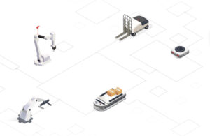
MOV.AI, which offers a robotics platform to develop AMRs and AGVs, brought in $8.2 million in funding.
Foxglove brings in $15M, updates 3D panel
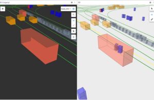
Foxglove, a company creating flexible, user-extensible developer tools, announced that it brought in $15 million in Series A funding.
Seegrid and Applied Intuition partner to improve AMR simulations
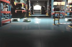
The two companies will push the envelope of the state of the art in AMR simulations.
KUKA iiQKA.OS promises to be easy to use

KUKA Robotics launches a new open source operating system called KUKA iiQKA.OS – designed from its core, to be easy to use. The new OS will initially be available on KUKA collaborative robots.
Managing large robotics software teams

Developing a robot is more complicated than a standard embedded software implementation. There are unique challenges to overcome to ensure that a robot will meet its requirements, function as intended, and be delivered on time and on budget. The teams developing robotics software must coordinate well within their own team while also working in parallel…
Rapid Prototype Trends

3D solid model software has come a long way. It makes complex finite element analysis an integrated feature so that new designs can be explored in hours, rather than days or weeks of building prototype parts and making changes. New product development costs have been falling consistently since the advent of this technology. The logical […]
Siemens PLM Mechatronics Software Derived From Video Games
Siemens PLM Software announced a new integrated machine design solution aimed at creating value for companies that develop and market machine tools and production machines. Mechatronics Concept Designer™ represents a paradigm shift for the industry with a new systems engineering approach to machine design that captures “voice of the user ” input, manages early requirements […]
Universal Robotics Lauches 3D Software Compatible With Webcams
Universal Robotics, Inc., a software engineering company, announced the launch of two simple-to-use 3D vision software products: Spatial Vision and Spatial Vision Robotics. The products can turn any pair of webcams into a highly accurate, cost-efficient 3D vision system that can be employed in virtually any setting without expensive equipment. With Spatial Vision and Spatial […]
Sartorius Introduces ProBatch+ Software

Goettingen, Germany — The Sartorius ProBatch+ software used in conjunction with the Sartorius X-Family, Combics Pro, and other PLC controllers offers the user efficient management of original raw material and recipe data. The powerful ProBatch+ software program allows for visual presentation of the running process and enables all batch procedures to be both visually monitored […]
Motion and Easy-to-Use

I get a little crabby about some of the things I have seen over the years in the motion control and especially the American marketing mentality. In particular, the words “motion control” and “easy to use” should not appear in the same sentence without great care and thought about the statements being made. If there […]
Danaher Motion Introduces MechaWare 3.0

SANTA BARBARA, CALIF — Danaher Motion introduces MechaWare 3.0 — the industry’s only mechatronic toolkit that seamlessly integrates mechanical systems and control software design resulting in faster design cycles, superior motion system performance, and faster time to market.
Better Software Tools
Better Software Tools Help Machine Builders Reap the Benefits of Mechatronics. Newer software programs intended for machine builders take advantage of mechatronic principles and easily blend the necessary and different engineering disciplines. By John Pritchard, Global Product Marketing Manager Kinetix Motion Control, Rockwell Automation Traditionally, machines have been designed and built using individual mechanical, control, […]
The Evolution of Motion Programming Devices
Here’s a closer look at software development for programming motion systems and how these choices affect software reusability. By Chuck Lewin Performance Motion Devices Software development can be the single greatest engineering cost for many machine design projects. This observation is especially true for motion control projects because of the inherent complexity of managing such […]