Tips for Improving Mechatronic Collaboration

February 14, 2010 by admin  
Filed under Commentary, Design, Technology

By Leslie Langnau, Managing Editor

The use of mechatronics principles should make new product/device design faster, easier, and deliver fabulous and inexpensive products. But many engineering groups grapple with this design approach. Why do some groups work while others struggle?

We’ve heard about the promise of mechatronics for many years. Off-the-record, we hear comments about the “problems with mechatronics.” Some engineering groups get it and apply it with great success. Others don’t even want to hear the term. But there is no denying that whatever you call it, this approach to design is necessary in today’s world of multifunction, multitasking equipment and systems.

You don’t have to refer to this approach as mechatronics. Said Kevin C. Craig, Ph.D., Professor of Mechanical Engineering, Marquette University, “I define mechatronics as multidisciplinary engineering system design.” This definition is much more descriptive.

A number of engineers and managers are looking into why this approach appears to either not deliver on its promises or why it only works for some. Their research so far indicates that there are three main problems: Education, corporate structure, and the lack of truly collaborative design tools.

Education should break down the walls, but …
Years ago, the wall between manufacturing and engineering had to come down before industry realized measureable improvements in productivity. A similar situation faces those who wish to implement mechatronics, only this time the walls that must come down are those between engineering disciplines.

Education has played a role in building those walls, partly in response to demands of last century’s corporations and labor unions who segregated engineering manpower into separate functions; mechanical, electrical, and others. Today, inertia maintains the status quo with many universities and colleges continuing to segregate engineering disciplines. Even the professors don’t collaborate with each other! The result is mono-functional engineers (a new term that you may hear more of soon).

This singular focus has created engineers who speak a different engineering language from each other. Noted John Pritchard, global product manager, Kinetix Motion Control, Rockwell Automation, “At a recent workshop with 50 engineers pulled from all areas of a company, the language discrepancies were clear. We were discussing how to take a mechatronic approach to robot design. In the conversation, the mechanical engineers spoke about their struggles with reverse dynamics. The control guys said their biggest challenge was Cartesian to joint transforms. This conversation went on for ten minutes before they realized they were talking about the same thing, just using different words. The control guys were thinking about math while the mechanical guys were thinking about links, angles, and so on. For this group, the solution was to speak mathematics.”

More collaborative software tools are coming that will move mechanical, electrical, and controls design information in both directions among the engineering groups.

A few educators are aware of this issue and are initiating a profound change, which we will go into shortly.

Another educationally based problem involves awareness; the decisions any engineer makes can affect other engineers’ choices for a design. “Lack of such awareness trips up many projects,” agreed Pritchard. “The choice of material is a fairly common decision that causes problems. For example, in the design of a reciprocating mechanism controlled by a servo system, a mechanical engineer may choose steel over aluminum. The steel may be more readily available, less expensive, standard practice, and so on. The control engineer, however, is now confronted by several constraints because of this choice. The servo motor must have three times the peak torque to accelerate at the same rate it would have needed had the mechanical engineer gone with aluminum. In addition, the design will need a bigger motor, bigger drive and circuit breaker, heavier wiring, bigger amp supply, bigger everything.

“The mechanical engineer may have no idea how the design of one part impacts the overall machine. A 10¢ per part saving may really result in up to $10,000 additional cost in order for the control engineer to deal with the larger inertia. And there are many choices like this; couplings, compliance, gearbos backlash, and so on,” continued Pritchard. “And the control engineers and the electrical engineers do the same thing; trapezoidal acceleration, for example, can excite resonances which can frustrate the mechanical engineers. Another example is the common practice of putting acceleration at 100% rather than a lower percentage, which can impact wear.”

Here’s an example of a mechanically oriented motion analyzer, the result of collaboration between Solidworks and Rockwell Automation.

“And control systems is one of the more important disciplines for mechanical and electrical engineers to have some knowledge of,” added Razvan Panaitescu, manager of Engineering for Mechatronics, Siemens. “It stands in between mechanical and electrical. You don’t need to know electronics deeply, just enough to model.”

A few professors have witnessed this lack of awareness and are developing programs that will not only solve it, but that will create shifts in the traditional engineering labor pool.

A change is coming
Ken Ryan, Director of the Center for Applied Mechatronics at Alexandria Technical College in Minn., spoke about what educational institutions can do to resolve these issues. He sees the engineering role shifting into two main categories: the specialist engineer (which is probably most of you) and the cross functional engineer.

The Specialist or mono-functional engineer is the traditional Mechanical Engineer (ME), Electrical Engineer (EE), Controls Engineer (CE) and so on. These individuals are experts in their chosen field. “Industry will always need these individuals,” said Ryan, “but not in the numbers that they have hired previously. I see a day when a company’s engineering labor force will consist of about 20% of these specialists.”

The Cross-Functional engineer is essentially the mechatronics engineer. This individual has more of a breadth of training, learning much about multiple engineering disciplines but typically not to the depth of the specialist engineer. These are the people corporations need to make mechatronics programs successful. Noted Ryan, “I think these people will make up about 40% of the engineering labor pool in a typical corporation.”

The cross-functional engineer can be further divided into two categories:

The Technologist: This individual is meant to be the functional extension of the traditional engineer; they implement the designs of the specialist. She/he is a member of a mechatronics team and will often function as a liaison among the specialists. This individual’s role is coordinative and integrative, both vertically and horizontally.

The Technician: This individual does what an engineer tells him/her to do. They are responsible for installation, service, and maintenance of mechatronically designed equipment. The remaining 40% of a corporation’s engineering pool will likely consist of these skills.

Mechatronics requires that either you master more than one or two engineering disciplines, or you develop a group of generalists to support the specialists. The cross-functional engineer will never replace the specialist engineer because they do not have a comparable depth of knowledge.

At Alexandria Technical College, the program is very successful. The college is in the middle of a huge packaging machinery area. By developing a cross-functional engineering program, graduate students find placement in all kinds of industry including transportation, mining, marine, automation, and other areas. “Once we took ourselves out of the packaging box,” said Ryan, “then we started finding lots of people interested in our students because these fields are all trans-functional fields.”

Corporate structure needs to nurture collaboration, not impede it
Global locations and engineers grouped by discipline do more to create miss-communications than solve it. “The biggest problem is interaction among disciplines,” noted Panaitescu. “Many corporations still physically group engineering disciplines so that engineers either work only with other engineers of their discipline, or they work in isolation.” The most successful companies have an open culture and nurture it.

Then there is the issue of cooperation, which can be sidetracked by corporate structure. “Engineers are naturally competitive,” said Panaitescu.

NI is also working on developing more collaborative design tools.

“But companies with more successful mechatronic design programs leverage the competitiveness between project-focused cross-functional engineering groups rather than having individual engineers competing against each other,” noted Pritchard. “The strategy of ‘which group will produce the best machine’ works well.”

Successful users of mechatronics also use a common design process that everyone sticks to. “One goal of a common design process is to ensure engineers check with each other throughout, ensuring that one decision does not impede future decisions from other engineers involved in the design,” said Panaitescu. “Corporations do not need to mandate that engineers attend communication classes; that is not the issue.”

Part of this common process involves the creation of a requirements document. It lays out in the beginning, what the design must do. Noted Panaitescu, “it is not often used because its not very interesting paperwork. But it can help speed product development.”

“The first step is to sit with the customer and decide what the device must do,” continued Panaitescu. “It will not significantly differ among projects. But if you define soundly, thoroughly, then everyone thrives. Naturally, the requirements will include performance, precision, timing, vibration and so on. But the requirements should also include how a system performs and how it will be designed; did you optimize that machine, reduce its carbon footprint? How much material did you put into the machine? These factors should be part of the mechatronics concept. The requirements change as we change. If you have such a process that incorporates physical mechatronics concepts with requirements concepts, then you have everyone in the team looking at the same goal, a common perspective.”

Proctor & Gamble, for example, has resolved many of these issues. Said Craig, “P&G has developed internal programs that have broken down the silos, embraced mechatronics, developed integrated design, and offer in-house courses that look at the mechanical, electrical, and controls. It’s doable.”

The need for truly interoperable software tools
The biggest issue with the various CAD and other product-development tools is that they do not offer the required level of interoperability that lets a controls engineer interact with the design of an electrical engineer.

“At first glimpse,” said Craig Therrien, product manager, Dassault Systèmes SolidWorks Corp., “it might appear that a simple movie of a machine in operation is all that is necessary for a collaborative mechatronics approach.

However, although a 3D-based mechanical CAD animation of intended machine function is a huge improvement over 2D drawings – and can help pinpoint potential collisions – it does not convey important engineering information that electronics and controls engineers need to select, size, and program the appropriate system. Nor can an animation alone help engineers factor the effect of their decisions into the mechanical design.”

Something more than moving pictures is needed to take advantage of mechatronics. Programs should provide control engineers access to mechanical engineering information, such as mass, material properties, moments of inertia, and force/torque requirements, to choose the most suitable electronic control mechanism. Mechanical engineers need to combine the loads created by specific electronic controls with the output of dynamics analyses to validate a system’s structural integrity. Controls programmers need to be sure the system functions as intended without any mechanical or electronics systems issues. In short, everyone involved needs an integrated mechatronics design environment that moves mechanical and controls design information in both directions. This helps the team to make important decisions and design modifications during the design cycle rather than as a result of costly prototyping.

Two soon-to-be-released examples of such a mechatronics environment are the integration between SolidWorks® Motion kinematics and dynamics analysis software and controls automation packages LabVIEW® from National Instruments and Motion Analyzer® from Rockwell Automation.

“With these integrated tools,” continued Therrien, “the mechanical engineer can model a machine in SolidWorks 3D CAD software and conduct kinematics and dynamics analyses in SolidWorks Motion software. Then, electronic systems engineers and control programmers can access the entire motion simulation from either LabVIEW or Motion Analyzer, including pertinent engineering data such as force, torque, and friction requirements, to design and program the control system. Finally, the mechanical engineer can access detailed controls information, such as the type of device or the size of the motor, to conduct additional stress and vibration analyses.

Noted Marc Monaghan, engineering systems manager at Hartness International, a manufacturer of packaging systems, “We are constantly looking for ways to reuse our design data, and the merging of mechatronic control simulation with mechanical design is an excellent approach. This integration extends the benefits of kinematic simulation into the arena of control programming, allowing the initial concepts of control logic to be designed and tested simultaneously with the mechanical function that it needs to control.

“Project timelines are more aggressive than ever, giving us much less time to develop designs with iterations of physical prototyping,” Monaghan added. “The integration of 3D modeling, analysis, and control development allows us to identify potential issues and opportunities for innovation long before the first part is produced. It is another step towards getting more problems solved during the design phase of a project, when cost savings and efficiency improvements deliver the most benefit.”

Engineers at NCR Ltd., a leading manufacturer of ATM machines, also desire and require better product design tools. According to Dr. John White, chief engineer at NCR, “We use mechatronics to optimize performance. An interoperable program, such as the SolidWorks and LabVIEW connection, gives our R&D teams the ability to develop a digital prototype in advance of a physical build. LabVIEW controls the motion trajectories while SolidWorks is used to calculate the driving forces, power requirements, and stresses. Connecting the control software to the mechanical assembly provides our engineers with the data needed for full design analysis and optimization. For us, it’s all about reliability through optimization.”

Dassault Systèmes SolidWorks Corp.
www.solidworks.com

National Instruments
www.ni.com

Rockwell Automation
www.rockwellautomation.com

Maxon Announces Strategic Collaboration with National Instruments

February 11, 2010 by admin  
Filed under Automation, Robotics, Technology

Maxon Precision Motors is pleased to announce a strategic collaboration with National Instruments (Austin, TX). The initiative will look to highlight mutual areas of interest in the field of robotics. An informal relationship between the two companies was initiated as early as 2006, with the inclusion of NI LabVIEW VIs in Maxon’s EPOS family of digital position and speed controllers. Most recently the two companies collaborated on the design and development of ViNI , an all inclusive robotics platform created by engineers at National Instruments. ViNI is driven exclusively by Maxon motors, gearheads and encoders and NI CompactRIO embedded controls.

“NI and Maxon have worked together to integrate the high productivity of NI LabVIEW graphical software and the high-precision drive systems of Maxon Motors so roboticists don’t have to assume the integration workload,” said Shelley Gretlein, Senior Group Manager of LabVIEW Real-Time & Embedded at National Instruments. “Also, with the release of LabVIEW Robotics software, design engineers now can access native Maxon Motor interfaces ready-to-run on their next autonomous system.”

Other notable robotic applications driven by Maxon motion control products include the Mars “Rover” by Jet Propulsion Laboratory, “Da Vinci” surgical robot by Intuitive Surgical and “DARwin” the humanoid robot developed at RoMeLa, the Robotics & Mechanisms Laboratory at Virginia Tech University.

Both Maxon and National Instruments recognize that advancements in each respective area of expertise are complementary and look to provide designers with state-of-the-art hardware and software solutions for developing new robotic products and applications. Several joint marketing efforts are slated for 2010. Maxon will continue to focus its R&D efforts on electric motors, sensors and motion controllers while National Instruments will leverage its LabVIEW platform, NI LabVIEW NI SoftMotion Module, and CompactRIO.

“It is an exciting time to be involved in the robotics industry. Over the years Maxon has directed a significant portion of our engineering efforts toward the development of specialized products for robotic applications, and we are just beginning to realize the benefits of our investment. We are pleased to be working with NI and their talented group of engineers”, states Kirk Barker, Electronics Product Manager.

CompactRIO, LabVIEW, National Instruments, NI, ni.com and SoftMotion are trademarks of National Instruments. Other product and company names are trademarks or trade names of their respective companies.

National Instruments
www.ni.com

maxon motor
www.maxonmotorusa.com

Increased Sensing Accuracy with Signal conditioning

October 13, 2009 by admin  
Filed under Technology, Test & Measurement

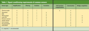
By Brett Burger, National Instruments, Austin, TX

Signal conditioning provides a distinct advantage because it enhances both performance and measurement accuracy.

For many real-world applications, you must measure environmental or structural parameters, such as temperature or vibration, with sensors. These sensors, in turn, require signal conditioning before a data acquisition device can effectively and accurately measure the signal. Signal conditioning provides a distinct advantage over data acquisition devices alone because it enhances both the performance and measurement accuracy of data acquisition systems.

Data acquisition systems

With the speed and accuracy of modern data acquisition devices, it is easy to overlook the need for signal conditioning. While plug-in DAQ devices specifically and accurately measure voltage signals, voltage is only one of many I/O types required by modern measurement and automation applications.

Many of today’s data acquisition systems must also measure signals from sensors that detect physical, chemical, or mechanical phenomena. While several of these sensors, such as RTDs and strain gauges, must have signal conditioning to return any measurement, they all require conditioning to return accurate measurements.

Fig 1. New signal conditioning systems can perform multiple sensor measurements in a single system.

Fig 1. New signal conditioning systems can perform multiple sensor measurements in a single system.

While data acquisition devices have become progressively more intricate, the basic principles of data acquisition remain the same — you must connect to the signal, apply the necessary signal conditioning, digitize the signal, and display the data (see Fig. 1). With this in mind, the three vital components of all data acquisition systems are as follows:
• Signal conditioning (to condition the signal/sensor).
• Data acquisition device (to digitize the conditioned signal).
• Software (to analyze, record, and display the acquired signal data).

The component most often forgotten, yet fundamentally important, is signal conditioning. A large portion of the world’s measurable signals must be detected with sensors, most of which require some sort of signal conditioning for the data acquisition device to accurately read them. Thus, a data acquisition system must not only incorporate the digitizer and application software, but also tightly integrated signal-conditioning hardware.

Improving accuracy

Data acquisition devices are used in a variety of applications. In laboratories, in field services, and on manufacturing plant floors, these devices act as general-purpose measurement tools well suited for measuring voltage signals.

However, for many real-world applications, you must measure environmental or structural parameters, such as temperature or vibration, with sensors. These sensors, in turn, require signal conditioning before a data acquisition device can effectively and accurately measure the signal. Signal conditioning provides a distinct advantage over data acquisition devices alone because it enhances both the performance and measurement quality of data acquisition systems.

To illustrate the necessity of signal conditioning, consider a thermocouple. To accurately measure thermocouple signals, you must provide amplification, filtering, and cold-junction compensation.

Amplification is required because of the small magnitude of the signal, and you must apply it as close to the thermocouple as possible to increase your signal-to-noise ratio. While this amplification help reduces the noise effect on your signal, you must also provide filtering to eliminate environmental noise from power lines and other electric devices.

Cold-junction compensation is also necessary to offset any temperature difference that exists between the measurement junction of the thermocouple and the junction with the data acquisition device. The net effect of this signal conditioning is dramatically improved accuracy.

Fig. 2. SCB-68 screw-terminal connector block.

Fig. 2. SCB-68 screw-terminal connector block.

Fig. 3. SCXI-1112 thermocouple signal conditioner.

Fig. 3. SCXI-1112 thermocouple signal conditioner.

The graph compares thermocouple measurements taken at 25°C using a National Instruments SCXI-1112 thermocouple signal-conditioning module and an SCB-68, a screw terminal connector block with a temperature sensor for cold-junction compensation (see Figs. 2 and 3). The SCXI-1112 module achieved an accuracy of 0.3°C, compared to 5.0°C accuracy with the SCB-68 (see Fig. 4). Thus, the SCXI-1112 signal-conditioning module provides a thermocouple measurement with accuracy more than 10 times greater than that of the terminal block because of preamplification, low-pass filtering, and a more accurate temperature sensor.

Fig. 4. This accuracy comparison shows that the SCXI-1112 signal-conditioning module delivered ±0.3°C accuracy compared to ±5.0°C with the SCB-68 terminal block using a calibrated input.

Fig. 4. This accuracy comparison shows that the SCXI-1112 signal-conditioning module delivered ±0.3°C accuracy compared to ±5.0°C with the SCB-68 terminal block using a calibrated input.

There are several critical signal conditioning technologies that enhance the accuracy and performance of the data acquisition system:

Amplification. Amplifiers improve the accuracy and sensitivity of your small signal measurements by boosting the amplitude of the input signal to better match the input voltage range of the digitizer, thereby increasing the resolution and sensitivity of the measurement. While many data acquisition devices include onboard amplifiers for this reason, many sensors, such as thermocouples,
require more amplification than a data acquisition device alone can provide. Using signal conditioning to amplify the signal near the source also reduces the environmental noise effect on your measurement.

Attenuation.
Attenuation diminishes your input signal’s amplitude to fall within the digitizer’s input range so you can measure high-voltage signals with your data acquisition system.

Isolation.
Signal-conditioning devices with isolation pass input signals to the measurement device by using transformer, optical, or capacitive coupling techniques rather than a physical connection. Isolation prevents ground loops. With isolation, you can measure signals with high common-mode voltages while protecting the expensive measurement equipment in your data acquisition system from any high-voltage surges that may occur.

Filtering.
Filtering improves your measurement accuracy by removing unwanted frequency components from your signal. In addition to eliminating noise from your measurement, filtering prevents signal aliasing (a phenomenon that occurs when frequencies higher than half of the sampling rate appear in your measured signal, corrupting your measurement).

Excitation. Many sensors, such as RTDs, strain gages, and accelerometers, require some form of power to return a measurement. Excitation provides this power, in the form of either voltage or current, so you can use these types of sensors in your data acquisition system.

Calibration. Calibration improves your measurement accuracy by adjusting your data acquisition system to compensate for any imbalances in your sensor or measurement hardware. For example, strain gage measurements require both null (or zero) and shunt (or gain) calibrations to ensure accurate linearization.

Cold-junction compensation.
Thermocouples measure temperature as the difference in voltage between two dissimilar metals. Based on this concept, another voltage is generated at the connection between the thermocouple and connector (or terminal) block of your data acquisition device.

Cold-junction compensation improves your temperature measurement accuracy by providing the temperature at this connection, which you can then subtract from the reading.

Simultaneous sampling.
When you must measure two or more signals at the same instant in time, you need simultaneous sampling. Using signal conditioning with track-and-hold circuitry can be a much more cost-effective simultaneous sampling solution than purchasing a digitizer for each channel. Typical applications that might require simultaneous sampling include vibration measurements and phase-difference measurements (see Table 1).

table-1

DAQ system considerations
The number of available data acquisition system devices and options can make the process of choosing the proper components very complex. But this process is crucial because the type of components you use can have a dramatic effect on the overall performance and accuracy of your system. Couple this with the fact that your development and time to first measurement also can be drastically impacted, and it quickly becomes evident that component choice is one of your most important decisions in selecting the right data acquisition system.

There are nine essential considerations for your data acquisition system that can help you take full advantage of the latest advances in computer-based data acquisition.

Breadth of signal types.
Selecting signal conditioning hardware that accepts a large breadth of signal types is critical to protecting your data acquisition system investment. In addition, the ability to incorporate all of these measurements into a single data acquisition system can dramatically reduce your development time because you can focus on implementing your tests rather than learning and configuring multiple measurement systems. To illustrate, consider an application where you must validate the design of an automobile engine. To accurately characterize the engine, you must measure a variety of signal types — including temperature, vibration, frequency (rpm), and torque — each with unique conditioning requirements. Traditionally, this meant that you needed an individual stand-alone instrument or custom data acquisition device for each type of measurement, which required you to configure multiple devices. With modern, high-performance signal-conditioning hardware, you can easily incorporate all of these measurements into a single, rugged chassis and configure them from a single software interface, such as NI-DAQ. This capability reduces your current application’s development time and cost while still protecting your data acquisition system investment and providing the flexibility to address future applications.

Connectivity. With the diverse range of sensor connectors available, your signal-conditioning hardware must not only offer a variety of connectivity options but also, more importantly, the specific options you need. Whether you are using a strain gage with a D-Sub connector or an accelerometer with a BNC interface, your signal-conditioning platform should offer easy connection to all of your sensors to simplify your system setup. Some signal-conditioning hardware offers direct connectivity options on a per-channel basis so you can match each channel to the required connector. With sensor-specific connectors, you can easily remove and replace individual sensors while your data acquisition system is still running, making it easier to troubleshoot your system and minimizing system downtime. On the other hand, the most flexible type of connector is the screw terminal. Consider a data acquisition system with screw terminals for voltage and current measurements or if your sensor connection type is likely to change often. When you can connect your data acquisition system to any sensor, you greatly enhance your measurement capabilities.

Expandability. As your test evolves and your measurement requirements change, you must have a data acquisition system that provides the flexibility to expand and change with your application. Expanding your data acquisition system should not require a complete overhaul of your signal-conditioning platform. Using modular signal-conditioning hardware, you can very quickly increase the number and variety of signals in your system by simply plugging in another module. This feature protects your data acquisition system investment because you can expand your channel count in a matter of minutes, dramatically reducing the time before your modified system is up and running. This flexibility, in turn, reduces the total cost of ownership for your data acquisition system.

Integration. To realize the full productivity potential and value of your data acquisition system, all of its components must integrate seamlessly. Specifically, your signal-conditioning hardware should be capable of incorporating mixed-signal types in a single system, while still maintaining quick and easy connection to your data acquisition device. With this capability, you can dramatically reduce your setup time. Furthermore, by selecting signal-conditioning hardware that tightly integrates with your data acquisition device, you can easily upgrade the speed and resolution of your entire data acquisition system as your application requirements evolve by simply upgrading the data acquisition device. Thus, tightly integrated signal-conditioning hardware can reduce both current and future system development costs.

Packaging. Your signal-conditioning hardware packaging is most often dictated by the size and environmental constraints of your application. Because space is at a premium on most laboratory and test floors, it is important to choose a data acquisition system that packs more channels into less space. Signal conditioning with high-channel density minimizes the space requirement of your data acquisition system while reducing per-channel cost. In portable applications, your signal-conditioning hardware must be compact and lightweight, while still offering a high level of performance and functionality. Alternatively, applications running in harsh, industrial environments require signal conditioning with rugged mechanical packaging. To operate effectively in such extreme environments, hardware must be capable of enduring a wide operating temperature range in addition to severe shock and vibration.

Software. A large portion of the total cost of a test and measurement system is application development. To keep these costs to a minimum, you must use software tools that maximize productivity. In particular, driver software should provide a single interface for configuring and testing your entire data acquisition system, while also tightly integrating with your application development environment (ADE). Driver software should also provide the ability to scale and calibrate your sensor measurements. These capabilities dramatically reduce your overall development time and cost because you can quickly incorporate new sensor measurements into your data acquisition application.

Isolation.
Isolation can dramatically increase the overall value of your data acquisition system by improving overall safety, accuracy, and performance. By creating an insulation barrier, isolation permits the ground reference of the input and output of a measurement device to be at different voltage levels, protecting both the operator and equipment from any transient voltage spikes. Isolation also improves system accuracy by physically preventing ground-loop currents, a common source of measurement noise and inaccuracy; ground loops result when a data acquisition system and its input signal have separate grounds at different potentials. Lastly, isolation improves the performance of your data acquisition system by increasing its common-mode rejection ratio (CMRR), or ability to reject common-mode voltage. Common-mode voltage, another frequent source of error, is voltage that is present on both the positive and negative input of your measurement device, but it is not part of the signal you wish to measure. While isolated devices are often more expensive, their additional cost is easily justified when you consider the amount of troubleshooting time isolation saves you by eliminating hard-to-find sources of error, such as ground loops and
common-mode voltage.

Calibration. One of the most critical technologies that a signal-conditioning system should incorporate is the ability to be easily and accurately calibrated. Most measurement devices are calibrated at the factory, but the accuracy immediately starts to drift with time and temperature changes. To make the most accurate measurements possible, you must periodically calibrate your entire data acquisition system. If your system has precision onboard voltage references, you can adjust your measurement system to compensate for temperature changes. In addition, you must have access to external calibration services to keep your system performing up to the manufacturer’s specifications year after year. It is very important to understand the calibration capabilities and requirements for any signal-conditioning system under consideration because this is the only way to ensure that your investment contains the technology you need to make accurate and reliable measurements.

Switching. In today’s demanding test environments, the ability to route signals easily throughout your measurement system is a technology that can lead to huge improvements in test times. As an example, consider a case where you must subject a unit under test (UUT) to four separate measurements in the testing process. Without the proper technology, you must reconnect the UUT to each different measurement device for each test. With state-of-the art switching technology, not only can you route the UUT leads automatically to each measurement device in turn, but also you can test several UUTs at the same time. You thus achieve more efficient use of your test equipment, faster test times, and less user intervention. Your selection of a signal-conditioning system that offers this technology can have a huge impact on the overall performance and cost of your system.

Bandwidth. Bandwidth is an often overlooked but extremely important technology to consider when selecting a signal-conditioning system. Modern signal-conditioning hardware should have the bandwidth to handle data throughput from a high-channel-count system and to accommodate any future growth in channel count. System bandwidth is typically expressed in samples/second (Hz), and often reaches several hundred kilohertz for large systems even at modest acquisition rates.

Overall, signal conditioning defines the measurement capabilities and is a critical component of any complete data acquisition system. Furthermore, signal conditioning is required for accurate sensor measurements. To protect your data acquisition system investment, you must invest in modular, easily expandable signal-conditioning hardware that accepts a wide variety of signal types and offers a broad range of connectivity options, while still meeting your size and environmental constraints and tightly integrating with your development software and data acquisition device.

The types of hardware listed in Table 2 are examples of National Instruments offerings. They serves as an example of the types of choices available to users when selecting signal-conditioning hardware capable of interfacing a signal or sensor to a data acquisition system.

Table-2

Front-end signal conditioning (SCXI)
SCXI is a signal-conditioning and data acquisition system for PC-based instrumentation applications (see Fig. 5). It consists of a shielded chassis that houses a combination of signal-conditioning input and output modules that perform a variety of signal-conditioning functions. You can connect many different types of transducers, including thermocouples, directly to the modules. The system is a high-performance USB plug-and-play data acquisition system, and it can also operate as a front-end signal-conditioning system for PCI, PXI, or PCMCIA data acquisition devices.

Fig. 5. Front end signal conditioning systems convert sensor measurements to a more standard 10V signal to be acquired by another data acquisition device.

Fig. 5. Front end signal conditioning systems convert sensor measurements to a more standard 10V signal to be acquired by another data acquisition device.

Integrated DAQ and signal conditioning (SC series)
SC Series data acquisition (DAQ) devices (see Fig. 6) expand the measurement capability of PXI by integrating measurement-specific signal conditioning onto a 16-bit PXI data acquisition device. With this tight integration of signal-conditioning and data-acquisition functionality, the SC Series delivers high-performance sensor-specific measurements at a lower cost per channel than leading solutions, such as SCXI DAQ systems, for low- to medium-channel counts.

Fig. 6. Combined Signal conditioning and DAQ devices are available for internal form factors such as PCI and PXI.

Fig. 6. Combined Signal conditioning and DAQ devices are available for internal form factors such as PCI and PXI.

Distributed DAQ with signal conditioning
CompactDAQ (see Fig. 7) and CompactRIO are modular embedded control and distributed I/O systems for measurement, control, and data logging. They are intended for applications that demand industrial-grade hardware with easy installation and configuration. Both systems feature built-in signal conditioning for direct connectivity to sensors and actuators. Modules are available for connecting to thermocouples, RTDs, strain gauges, 4 to 20-mA signals, high-voltage sources, and many other signals.

Fig. 7. New signal conditioning instrumentation can be customized or expanded by adding different modules.

Fig. 7. New signal conditioning instrumentation can be customized or expanded by adding different modules.

They offer embedded control by running LabVIEW Real-Time on a dedicated embedded processor, and can connect to a PC through a variety of industrial buses (Ethernet, serial, CAN, and Foundation Fieldbus) or even wirelessly (see Fig. 8). They can operate in harsh environments with electromagnetic noise, wide temperature ranges, and high shock and vibration.

Fig 8. Decreasing size and power requirements for signal conditioning help enable wireless test devices.

Fig 8. Decreasing size and power requirements for signal conditioning help enable wireless test devices.

National Instruments
www.ni.com

Hope For the Future

October 13, 2009 by admin  
Filed under Commentary, Robotics, Technology

By Richard Comerford, Editor, Electronic Products

One of the most frustrating things that we experience in our day-to-day existence is not being understood. As engineers, we’ve all run into people who have no idea what it is we actually do, and seem totally ignorant of the basic scientific principles and techniques we use every day. And those of us who have been around awhile may be tempted to tell those who are experiencing this frustration for the first time that it won’t be the last time they run into the situation.

mimeattachment

But recently I was given hope that the aforementioned situation may really be changing – that in the future, what we do as engineers will be less foreign to the world in general. The occasion was NIWeek, an annual meeting in Austin, TX, sponsored by National Instruments.

For those of you who haven’t attended this event – and if you really want to keep up with what’s happening in mechatronics you really should go to this show – the program includes opening keynotes each day that are a significant departure from the usual. Instead of someone just talking to you about technology developments, keynote speakers provide live demos of what the technology they’re working on can do. (You can see these keynotes at National Instruments’ Web site, http://www.ni.com/niweek/.) One of the keynote speakers, Ray Almgren, NI Vice President of Academic Marketing, made the following observations: “Through our work with LEGO, we’ve learned that kids are born with an innate sense of creativity. They are innovators; they are engineers – from the time they are born.”

Acting on that realization, NI is actively going about encouraging the development of engineering abilities, not only at the university level, but in high schools and elementary education institutions. They are a major contributor to FIRST (www.usfirst.org), a not-for-profit organization, founded by Dean Kamen, that aims to inspire young people to be leaders in science and technology; it does so by sponsoring robotics competitions that are like scientific Olympics, complete with team uniforms and a large stadium for competitions.

NI has also been working with LEGO to create toys that preschoolers and kindergarten kinds can use to build and program simple robotic systems. And they are backing a competition called Moonbots (www.moonbots.org) in which small teams composed of children and adults compete to design, program, and construct robots that perform simulated lunar missions similar to those required to win the $30 million Google Lunar X PRIZE, a private race to the Moon to encourage commercial exploration of space.

The dedication of  all those involved with these projects gave me hope that perhaps that feeling of being misunderstood just might disappear in future generations. “We are creating a new generation of engineers and scientists,” said Almgren, and that generation may not only make me feel more comfortable, they just may solve a lot of the world’s problems. As Almgern noted, “they are the real stimulus package.”

Robots created by high schoolers compete in a FIRST event.

Developing a two-wheeled self-balancing transport platform

February 10, 2009 by admin  
Filed under Motion Control

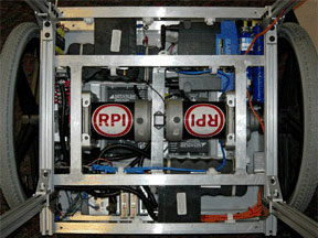
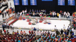
Annals of a mechatronic system design project

By Professor Kevin C. Craig and Matthew A. Rosmarin
Rensselaer Polytechnic Institute

feb-pjm-7
Figure 1. The Engineering System Investigation Process.

A senior design team at Rensselaer Polytechnic Institute (RPI) set out to develop an interdisciplinary mechatronic system by designing and prototyping a two-wheeled robotic locomotion platform inspired by (and with the permission of) the Segway Corporation, maker of the Segway Human Transporter. The two-wheeled, self-balancing transport platform utilizes parallel-wheel locomotion to provide precise maneuverability while maintaining system stability. The team tackled both the complexity involved in modeling, analyzing, and controlling the platform, as well as the implementation of two fully operational prototypes in a four-month time period.
Read more

The Cutting Edge of Haptic Research

October 17, 2008 by admin  
Filed under Motion Control, Robotics

Using tools such as graphical system design, reserachers are developing new, safer ways of interacting with machines that also permit more efficient operation

By Gerardo Garcia, Product Manager
Ben Black, Systems Engineer
National Instruments

Have you ever played a car racing video game that shakes when you go off-road? If so, you have interacted with a haptic interface. The word haptic comes from the Greek haptikos, which means to touch, grasp, or perceive.

Read more