Early Bird Registration for the Robotics Summit and Showcase ends on April 20th, 2018. Register by April 20th and receive a 20% discount to attend the event. The International Technical Design and Development Conference for Robotics and Intelligent Systems May 23-24, 2018 – Boston MA Agenda | Keynotes | Speakers | Sponsors | Register…
Matching Motor to Load – The first step in getting motion systems right

Motion control solutions are primarily mechanical in nature. If the mechanism is right for the load, the motion solution can be designed to meet the project objectives without difficulty. The starting point for this process is the selection of the motor. In keeping with the mechanical nature of the problem, consider that across all of […]
Servo Tuning

Making an electric motor operate correctly is as varied and complex as the millions of ways we use electric motors. Most of the time it’s just a matter of turning the motor on with a switch and letting nature take its course. Nature in this case as defined by Maxwell and Faraday. But when the […]
Optimizing Motion

Optimizing a motion control system is not easy. There are many tradeoffs that need to be considered. The strategy needed for each situation tends to be unique based on the problem that is being considered. One strategy involves speed, torque and time. These three variables are a connected system that is defined as the mechanical […]
Changing Landscape

Over the last few years there have been a number of changes in the cost of technology that are impacting the motion control marketplace. The first is the cost of microcontroller technology that is dedicated to electric motor applications. Up until recently, the Digital Signal Processor was the “de facto” standard for motor control. Not […]
Fast, Faster, Fastest – Or Not?

Speed is relative. Especially in the world of industrial control. 1 millisecond look ahead features in the machine control world used be considered “cutting edge” (pun intended). The programmable controller, the standard of industrial control, has a speed of execution metric. It is generally specified in thousands of instructions per millisecond. At 1000 instructions every 2 […]
Motion Feedback, Still Changing

The only constant in the world of motion control seems to be change. One of the most crucial aspects of motion control is the feedback mechanism. After all, if we can’t measure where we are, we cannot control it. The first order of business is to estimate what feedback resolution will be needed for the […]
Motion Control or Mechatronics, What’s in a Name?

Are we talking about Motion Control? or are we talking about Mechatronics? Words are important in describing reality and communicating with others. The term Mechatronics was coined a few years ago, possibly from the frustration that the term Motion Control does not adequately cover the subject. It is, however, a made up word. And as […]
Accuride Expands Heavy-Duty Slide Options
Accuride presents models 7950 and 7957, two new slides designed to expand the company’s heavyduty slide line-up and provide an intermediate load rating choice between the 3600 and 9300 products. The 7900 slides offer full extension, a load rating up to 350 pounds, and accommodate drawers up to 42″ wide. For added versatility, the slides […]
Out Of The Gait: Robot Sets Untethered ‘Walking’ Record
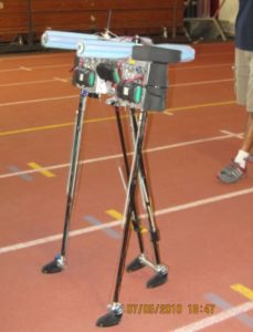
The loneliness of the long-distance robot: A Cornell University robot named Ranger walked 14.3 miles in about 11 hours, setting an unofficial world record at Cornell’s Barton Hall early on July 6. A human – armed with nothing more than a standard remote control for toys – steered the untethered robot. Ranger navigated 108.5 times […]
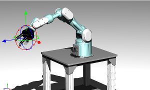
Igus Develops A Simpler Robotic Bionic Joint
When it comes to robotic joints, engineers have had to put together complex custom configurations out of multiple components, which involved considerable development time with the mechanisms. This time requirement often reduced the amount of time artificial-intelligence programmers had with the system. So, two goals of robotics developers were to enable the programmers to be […]
Torque, Control and Adaptive Gain
Torque is a very important aspect of motion control. Torque in a car (electric or combustion powered) is what turns the tires. Torque control is the ability to control the amount of torque needed based on conditions of the application. In the car, starting torque requirements can be very high, depending on how fast you […]
Air Bearings
Most things that turn, do so on bearings. Over the years, much attention has been paid to the bearing. The basic ball bearing has been mastered to reduce friction to incredibly low levels. The automotive drivetrain would not be possible without the friction reducing ability of the ball bearing. Accuracy in machining of the bearing […]
Six degrees of freedom and high precision
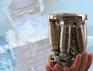
Parallel kinematics (PKM) precision positioning systems have many advantages over serial kinematics stages, such as lower inertia, improved dynamics, smaller package size and higher stiffness. Hexapods, a type of parallel kinematics positioning system, can move masses of 50, 200 or even 1000 kg with micron accuracy such as that required in medical applications. This particular […]
CUI Launches Updated Website for AMT Encoder Series
TUALATIN, OR – CUI Inc announced that it has launched a new version of amtencoder.com, a website dedicated to their proprietary AMT modular encoder series. The site now features detailed product pages, a resource area with technical documents, videos, frequently asked questions, a news section, and an inventor’s bio. CUI’s VP of Marketing Jeff Schnabel […]
Motors are Strategic Technology
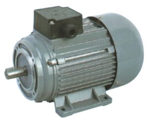
The 2007 Department of Commerce Census data is just now being released (how’s that for government efficiency?) and the good news is that the sector of the economy that manufactures electric motors and generators, a lot of which is used in industry for motion control applications, was up over 2002. The increase in total revenue […]
Electric Vehicles and Electric Motors
A friend of mine finally got delivery of a Tesla Roadster. This prompted discussion of the drive train and the fact that Tesla has had to go from two speed transmissions which were failing to a transmissionless drive train. The ultimate mechatronic challenge, the electric car, is also a challenger in terms of the precise […]
Super Size my Motor?
There is an interesting problem with applying electric motors that is a constant source of difficulty, the nature of peak power versus continuous power. The problem is that few systems operate at a statistical average power demand. Frequently, this causes equipment designers to oversize the motor for the application. At the same time, however, this […]
Top 10 Mechatronic Challenges
I recently wrote on the mechatronic challenge of wind power. Converting wind into mechanical power that can be harnessed for man’s use has been going on since the 9th Century according to Persian historians. Certainly wind powered grinding of grains has been around in Europe for several centuries and, lest we forget, wind power pumping […]
Linear Feedback Technology (Linear Motion Part 2)
Linear motion is particularly impacted by the choice of feedback. And for most systems the use of feedback is not an option. Linear motors, for example, cannot be operated without a feedback device. And because of the linear motor’s roots in semiconductor manufacturing, the feedback is usually a high resolution linear tape scale. How much […]
Linear Motion
Electric motors are generally rotating machines. And over the roughly 100 years of electric motor history, incredible effort has been put into adapting the technology to do an almost infiinite array of tasks. Which is why it’s kind of ironic that in the industrial world, a significant number of applications require the conversion of rotary […]
Time – Part 2
Time is the single variable that ties all of motion control and mechatronics together. And if that is so, its impact on our design work cannot be underestimated. The most basic feature of time is its relationship to work. The work done in a mechatronic system is defined through displacement over time. So a bunch […]