
3D solid model software has come a long way. It makes complex finite element analysis an integrated feature so that new designs can be explored in hours, rather than days or weeks of building prototype parts and making changes. New product development costs have been falling consistently since the advent of this technology. The logical […]
Out Of The Gait: Robot Sets Untethered ‘Walking’ Record
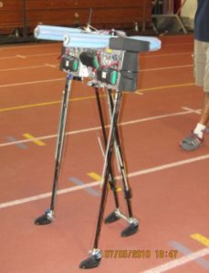
The loneliness of the long-distance robot: A Cornell University robot named Ranger walked 14.3 miles in about 11 hours, setting an unofficial world record at Cornell’s Barton Hall early on July 6. A human – armed with nothing more than a standard remote control for toys – steered the untethered robot. Ranger navigated 108.5 times […]
Igus Develops A Simpler Robotic Bionic Joint
When it comes to robotic joints, engineers have had to put together complex custom configurations out of multiple components, which involved considerable development time with the mechanisms. This time requirement often reduced the amount of time artificial-intelligence programmers had with the system. So, two goals of robotics developers were to enable the programmers to be […]
Mechatronics as Process
There are three basic disciplines of control. Discrete control which generally relates to making a product or dealing with sequential and event driven logic, process control which deals with the conversion of raw materials into more complex bulk products, and real time control of things like electric motors. In general, discrete control is not really […]
Personal CNC?
There has been a thread going through my mind involving the general field of machinery. The design of specialty machinery requires a great many disciplines, truly a mechatronic endeavor. Over the years, machine tool makers constantly worked on making the machines more complex in order to serve the market with greater functionality. In fact […]
Tips for Improving Mechatronic Collaboration
By Leslie Langnau, Managing Editor The use of mechatronics principles should make new product/device design faster, easier, and deliver fabulous and inexpensive products. But many engineering groups grapple with this design approach. Why do some groups work while others struggle? We’ve heard about the promise of mechatronics for many years. Off-the-record, we hear comments about […]
Custom Transfer System Adds Value by the Millisecond
Services and products from hydraulics, pneumatics, electrics, and linear technology were linked by Rexroth engineers to produce a custom engineering concept for Swiss company Mikron Machining Technology. “The fact that Rexroth offers coordinated components from pneumatic, hydraulic and electric drive technology right through to high speed control enabled us to select the most suitable characteristics […]
Magnets aren’t US anymore

The permanent magnetic is a quiet, unobtrusive work horse in so many applications that it, like many things that are mechatronics related, is mind bogglingly (is that a word?) pervasive. Magnets are the key material technology to enable high efficiency and power dense electric motors. And electric motors are everywhere. The particular magentic material that […]
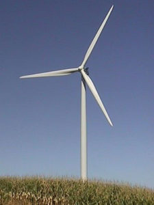
Big Wind Machines
Recently I had occaision to discuss the merits of wind power with a colleague. In particular there is a controversy between horizontal axis wind turbines, the giant propeller driven systems you see in advertisements, and vertical wind, which does not have much presence in the marketplace. The premise is that horizontal systems can take advantage […]
Make the Right Design Moves with Mechatronics

By Mark D. Hinckley, Director-Mechatronics, SKF USA Inc. Many electro-mechanical systems can qualify as mechatronic systems. Don’t agree? Take a look at these application examples that demonstrate both the power and potential of mechatronics in action. Mechatronics integrates mechanical and electronic technologies with application-specific software to perform a particular task. Engineers who use mechatronic components […]
Hope For the Future
By Richard Comerford, Editor, Electronic Products One of the most frustrating things that we experience in our day-to-day existence is not being understood. As engineers, we’ve all run into people who have no idea what it is we actually do, and seem totally ignorant of the basic scientific principles and techniques we use every day. […]
Batteries of the Future
Battery technology has been getting a lot of focus in the last couple of years. After all, you can’t have a decent electric car (or hybrid for that matter) without having the right kind of battery. And, just one more time, battery technology is what prevented the marketing of the electric car after the oil […]
Electric Vehicles and Electric Motors
A friend of mine finally got delivery of a Tesla Roadster. This prompted discussion of the drive train and the fact that Tesla has had to go from two speed transmissions which were failing to a transmissionless drive train. The ultimate mechatronic challenge, the electric car, is also a challenger in terms of the precise […]
Mechatronic Top Ten – Hard Disk Drives
One of the mechatronic Top Ten applications has to be the hard disk drive. Strangely, it is not an application that you hear much about. That’s probably because unless you work on hard disk drive design, you pretty much take for granted that little black box that stores all your information. So the group that […]
Top 10 Mechatronic Challenges
I recently wrote on the mechatronic challenge of wind power. Converting wind into mechanical power that can be harnessed for man’s use has been going on since the 9th Century according to Persian historians. Certainly wind powered grinding of grains has been around in Europe for several centuries and, lest we forget, wind power pumping […]
Linear Motion
Electric motors are generally rotating machines. And over the roughly 100 years of electric motor history, incredible effort has been put into adapting the technology to do an almost infiinite array of tasks. Which is why it’s kind of ironic that in the industrial world, a significant number of applications require the conversion of rotary […]
Mechatronics on the Trail of Global Warming

By Donna Sandfox Omron Electronic Components, LLC A new highly portable mechatronic system to measure harmful pollutant relies significantly on a MEMS flow sensor Figure 1. Stationary Aethalometers are used throughout the world, but have been too heavy to be truly portable until now. Carbon dioxide is well known as a major contributor to global […]
Mechatronics and Ignorance
By Richard Comerford, Editor Electronic Products I wish I had a dollar for each time I asked an EE about the use of mechatronics for a development project and got the response, “What’s that?” And I’m not just talking about IC designers, but about people involved with designing electromechanical systems like disk drives, as well […]
Wind Energy and Mechatronics
By Steve Meyer, CEO/Senior Consultant Solid Tech Inc. What would you put on a “Top Ten” list of the toughest mechatronic applications of all time? The electric car, plug-in or hybrid is certainly on the list. One application that needs to be on the list is the Wind Turbine. It is a mechatronic challenge because […]
Materials and Motion
Most motor sizing programs deal with time and torque analysis. The traditional tradeoff is more torque for less time. As an aside, the increase in electric motor torque comes with increased motor inertia, so it’s not for free. And the motor costs are always a factor. But this assumes that inertia is fixed. And that’s […]
Zuken Implements Mechatronics Design Strategy and Launches New 3D Modeling Solution

Munich, Germany and Westford, MA, USA – Zuken has made another step to strengthen the link between the electronics and mechanical design worlds by enabling parallel MCAD/ECAD design with a new collaborative software tool called Board Modeler. This forms part of company-wide strategy underway to deliver increased versatility and reliability between the mechanical, electrical, and […]
Tips for the Control Side of Mechatronics
By Leslie Langnau, Managing Editor Design World In mechatronic projects, the focus is often on the mechanical and electrical aspects of a system as engineers concentrate on throughput, speeds, accuracy, and so on. How these system goals affect the desired control selection may not be addressed until too late to make changes. Mechanical engineers do […]