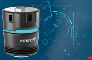
Bosch Rexroth hopes to help industry keep up with rising demands by making robot tooling more flexible and easier to use.
Bosch Rexroth opens production plant in Mexico
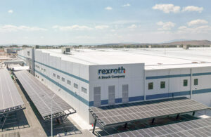
Bosch Rexroth opens a new plant in Querétaro, Mexico to complement the activities at the established sites in North America.
Bosch Rexroth acquiring majority of cobot maker Kassow Robots
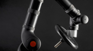
Bosch said the acquisition enables it to offer one-stop solutions, especially for the consumer goods and mobility industry including battery production as well as for the semiconductor production.
Bosch Rexroth and Geek+ partner on mobile robot development

Geek+ and Bosch Rexroth, both of which are among the largest suppliers of autonomous mobile robots and drive and control technologies, respectively, are collaborating on logistics robotics.
Making the correct robotics choices at the best price

Because of the many options in the field of robotics, end users sometimes face a dilemma in choosing between entry-level and high-performance features. People have different perceptions of how to define performance, speed, power or expensive controls. The best approach is to use a defined set of sizing and selection criteria to determine the required […]
Doing the heavy lifting: when Cartesian robots make the most sense
Compared to a Cartesian robot, a SCARA or six-axis system will generally deliver higher performance out of the box at a higher cost and with greater programming requirements, but with a smaller footprint, less weight and less rigid arm extension. On the other hand, a Cartesian system provides building blocks to create a solution that […]
6 things small manufacturers need to know about Cartesian robots
1. They handle heavier loads—A 20 kg payload is no problem for a Cartesian robot, which makes money savings possible by downsizing mechanics, using smaller components and less complex controls. 2. They fit tough orientations—A Cartesian robot is able to achieve the required precision when space is tight. 3. They widen travel range—Cartesian robots work […]
Rexroth EasyHandling brochure describes approach to designing and implementing handling systems

Bosch Rexroth has published a brochure describing the EasyHandling solution, a comprehensive platform of components, drives and engineering software. Rexroth’s EasyHandling system is more than a modular set of mechanical components, it completes the evolutionary transition from high-quality electrical and mechanical elements to a comprehensive system solution built on standardized interfaces and interoperable controls. The brochure […]
The Top 5 Mechanical Considerations For Electrical Engineers
Problems can arise in a mechatronics project because mechanical and electrical engineers often do not have sufficient experience or understanding of their counterpart’s discipline. Here is one application engineer’s advice on how to avoid five of these common problems when specifying parts for an electromechanical system. Getting the right motor is critical, which means matching […]
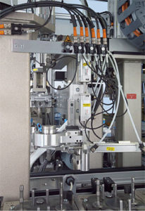
Custom Transfer System Adds Value by the Millisecond
Services and products from hydraulics, pneumatics, electrics, and linear technology were linked by Rexroth engineers to produce a custom engineering concept for Swiss company Mikron Machining Technology. “The fact that Rexroth offers coordinated components from pneumatic, hydraulic and electric drive technology right through to high speed control enabled us to select the most suitable characteristics […]
Mechatronics: New answers call for new questions
By Richard Vaughn, Product Engineer Bosch Rexroth Corporation–Project Management Dept. In a short time, mechatronics has evolved into a universally accepted engineering concept. It integrates mechanics with electronics – and with engineering itself. The result is expanded technological capabilities and assembly-line successes like the Cartesian multi-axis robot. Because it enables more flexible automated production, users […]