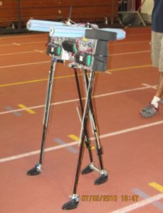
Linear Feedback Technology (Linear Motion Part 2)
April 19, 2009 by Steve Meyer
Filed under Automation
Linear motion is particularly impacted by the choice of feedback. And for most systems the use of feedback is not an option. Linear motors, for example, cannot be operated without a feedback device. And because of the linear motor’s roots in semiconductor manufacturing, the feedback is usually a high resolution linear tape scale.
How much feedback resolution is enough? Most of the time more resolution is better. But there is an element of control theory that says if the feedback resolution is ten times greater than the position accuracy that you are trying to measure, the control system can become unstable. The other side effect of extremely high resolution feedback is the tendency to “jitter” because it is responding to tiny variations in the real world, which the control system will then have to contend with. So spending extra money for high resolution feedback may cause other problems.
Where should the resolution be put? Obviously, if you are using a rotary servo motor, just use the feedback on the motor as the linear position reference. This works when the required resolution is not very high because in all mechanically linked systems, there is lost motion called backlash between the motor and load. But most motion controllers and many indexing drives contain dual feedback loops, so using an external feedback sensor will produce great benefit in accuracy and repeatability.
The big benefit in using linear feedback is the elimination of mechanical error as part of the control system. On a project I did a few years ago we were evaluating a special grinding machine that had a 13 foot long lead screw in it. The customer know the lead screw had wear and error in it, and that was part of the problem that needed to be addressed in rehabilitating the machine. Instead of replacing or re machining the lead screw, we specified an external linear tape scale feedback. The results were fantastic. Accuracy and repeatability were phenomenal and combined with an integrated servomotor system, led to a 300% increase inthroughput for the customer. Backlash? What Backlash?
How much distance do we need to sense? Some linear motors like piezo-electrics and voice coil motors have very limited stroke lengths. Similarly, different feedback technologies have scalability parameters such as sensing airgap and length requirements are considered. Some feedbacks work in the range of 2 to 6 inches in overall stroke length, some are capable of 3 feet, some up to hundreds of meters.
The exception is the stepping motor and leadscrew combination which can be operated without feedback on the assumption that the load is not varying dramatically. But even the leadscrew and stepping motor needs feedback when the load varies. Current detection can be used to determine if the motor has stalled, but doesn’t necessarily give you the opportunity to recover position without an external source. So the extra cost of external feedback is a judgement call based on the accuracy requirement and how “robust” the system needs to be.
The variety of types of linear feedback are equally challenging, and as with most things, must be considered based on cost and performance. The most popular feedbacks are linear tapescale systems that use reflected infrared beams that are interpolated to achieve very high accuracy. The classic linear feedback from the machine tool era is the glass scale which uses through beam optics and a grating embedded in glass to product the linear position information. Check out companies like Renishaw, Heidenhahn and others for details. Information on Heidenhahn’s latest innovation is featured on the Project Mechatronics website.
Over the last few years there have been a number of magnetic solutions where a magnetized linear scale is interpolated by taking the sinusoidal waveforms produced by Hall sensors or inductors, and digitizing the results. Integrated circuitry combining Hall effect arrays and functional support to linearize output are now the prevailing state of the art. Check out NewScale Technologies Tracker product for details on their new offering.
Time – Part 2
January 19, 2009 by Steve Meyer
Filed under Automation, Motion Control
Time is the single variable that ties all of motion control and mechatronics together. And if that is so, its impact on our design work cannot be underestimated.
The most basic feature of time is its relationship to work. The work done in a mechatronic system is defined through displacement over time. So a bunch of important variables get picked up. The force exerted in mechanical terms can be a torque for a rotating load or thrust for a linear load. The torque of a rotating load is the same as the current through the motor and drive. And this makes sense of why these performance characteristics are related.
The power rate of electricity usage is the Kilowatt Hour. The measure of work done over a period of time.
The horsepower is the mechanical unit of measure of work. One horsepower is the work done to move a 550 pound load 1 foot in one second. One horsepower is the equivalent of 746 Watts. Now we have a direct correspondence between the mechanical and electrical definitions.
If electric motors are rated in horsepower, the implied property is the amount of work that can be done using that motor to power a load. And an interesting anomoly occurs. In most situations the motor is built based on an arbitraty size, like 10HP, and not based on the load requirement, unless the application has sufficiently high volume to merit a custom design. A hard disk drive spindle motor is a case in which, because of the millions of units that will be sold, the motor design is unique. So its construction is specifically designed for the load it is applied to, the hard disk platter turning in a vacuum.
So in general application, electric motors are poorly matched to their loads because of the economics that drive motor manufacturing. The mis-match can be speed matching or power matching. This impacts energy efficiency more than the inherent efficiency of the motors themselves. Efficiency data is usually measured at rated power and can fall off dramatically for all load conditions less than maximum power.
The Power Rate of the system is directly related to the specification of the power semiconductors and mechanical contactors that are used to control motors. So when we think of torque being equal to amperes, the current rate dI/dt is the power rate throught the electronics side of motor control. In fact, the definition of the failure threshold in the power semiconductor, also called shoot through, is dI/dt.
Thinking about the relationship of torque and time, what happens when we consider acceleration? Acceleration is measured in units per second squared. Exponential. So when we start pushing system performance for a given load, as the allowable time for the motion decreases (cycle time decreases or throughput increases) then the torque requirement goes up exponentially, and the current requirement goes up exponentially as well. This requires a big increase in motor and drive size and cost, and in some cases reducing cycle times cannot be achieved.
Unless you change the inertia of the load. Aluminum is one third the mass of steel, and engineering plastics are often half the inertia of aluminum. So when you have the need for speed, don’t overlook material substitution as part of your strategy.
Safety Automation Sales to See Growth Through 2012
August 7, 2008 by admin
Filed under Automation
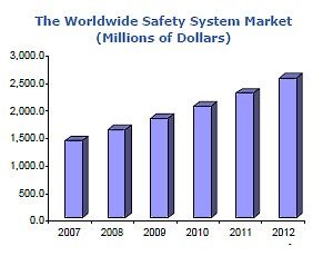
According to an ARC Advisory Group report, process safety system market shows unprecedented growth. ARC Advisory Group reports in Process Safety System Worldwide Outlook – Market Analysis and Forecast Through 2012 strong growth of the Safety Instrumented Systems (SIS) market. But due to the economic downturn in North America, the growth rate will be tempered after 2008. The worldwide market, around $1.4 billion last year, is expected to grow at a compounded annual growth rate of more than 12 percent per year to beyond $2.5 billion in 2012.
“The safety system market has experienced unprecedented growth for the last two years. Increased demand for oil and gas due to the economic growth of China and India along with the high price of crude oil is fueling investments in oil and gas production and in refining, leading to increased demand for safety systems,” said the principal author of the study ARC vice president, Asish Ghosh.
The greatest demand for safety systems is in the EMEA region, followed by Asia and North America. With booming economies in China and India, Asia will show the highest growth. EMEA will also grow substantially as the high price of crude oil leads to significant investments in grass-root facilities in the Middle East and parts of Europe.
Source: Control Engineering

